But, as usual, there is problems… What can you expect? nothing is perfect.
My current hypothesis is that the rpi is losing wifi connection for a very short period of time, causing the python code to save ‘garbage data’ that then Matlab interprets it a NaN (not a number)… and ergo the glitches.
Thats why I’m asking to the IT guys at my university if they can put a special router only for the MAST Lab… lets see if they deliver.
Pro Tip: Do not use EDURAM for sending/receiving at high rates UDP packages… or the gods of the glitches will punish you.
This educative video shows how a quadcopter is born, and of course its maiden flight.
I had to built a quad with some parts we order from hobbyking, so, I took my camera, put it in a tripod, read some instructions in the internet on recommended settings for stop motion videos, talk with my buddy Murray about cameras and lenses… and then, a quadcopter was born!!!!
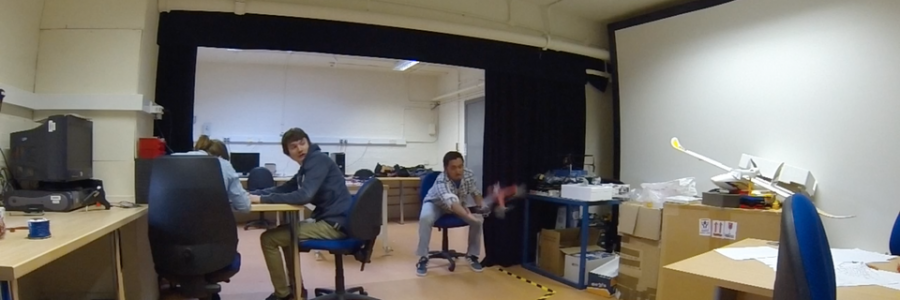
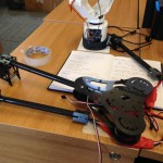
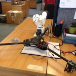
This large video is about the project that Murray and me have being doing in the MAST Lab. It’s about doing automatic position control and trajectory tracking of a micro unmanned aerial vehicle, being more specific is our 3D printed quadrotor platform, called TEGO, showed in previous posts here and here.
MAST Lab Fleet
The video explains almost straightforward what we are doing, but in a simple way, we are replacing the human pilot with a computer controlled one. The “artificial pilot” receives the very precise position of the markers onboard TEGO coming from the motion capture system and it computes the commands necessary to make those markers move to a desired position. Pretty simple and easy right? well… it its not! I’ll continue explaining part by part of the system.
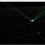
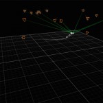
MoCap tracking
MoCap Tracking TEGO
Motion Capture.
We have a Optitrack system with 18 cameras, we have the Flex 3 ones, so, nothing too fancy, but for now, they are doing the job. The system is tricky to make sure is working perfectly, and usually the cleaning staff knocks one stand and then we have to do the “rain dance” over and over again, kind of stressful, in the pictures you can see using the interface from Natural Point the position of the cameras while tracking markers.
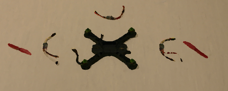
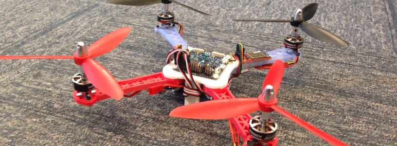
TEGO quadcopter
Our trustworthy platform, 300 grams with battery, 7-8 minutes of hovering, SK3 3100kv 42 watts motors, 10 amps ESC, 5×3 props, Rotite’s included on the frame.
Flight controller
Multiwii AIO v2, using MW firmware r1648 with Alex Kroroshko experimental PID algorithm, everything else is standard, rate = 0.9 and expo 0.3 for pitch and roll. I have to mention that I have received lots of help on the MW forums, so, thanks for that guys!!!
Wireless link
A pair of good old 3DR radios using a special firmware adjusted for the multiwii serial protocol (Andrew Tridgell’s SiK telemetry radio software for MultiWii). Oh and by the way, how cool is Andrew Tridgell!!! he is revolutionising everything, take a look at this awesome video. This radios are working at 115,200 bps, but we think that we might have a bottleneck problem while sending commands, maybe we just need more speed to achieve the trajectory tracking performance that we want…
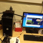
Ground Station
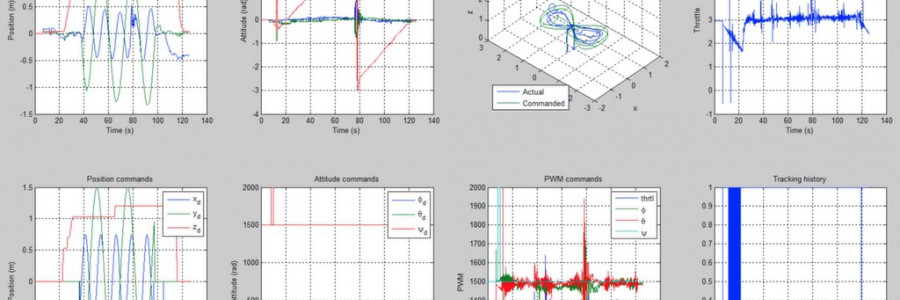
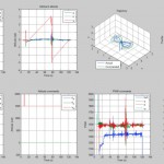
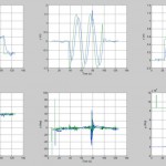
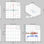
Figure of 8
Performance
Line trajectory
Matlab / Simulink, also you can see some pictures of the diagram and you can see it in action on the video. Why Matlab?? because we have a very convenient block for optitrack that makes our lives easier. We know that simulink is not famous with its performance when doing this kind of stuff, but it kinda does the job. Special thanks to my students Krisjanis and Davide for helping in the implementation of the MW serial protocol in simulink 🙂 you rock guys!!
The system is not perfect, we want to have a perfect performance, rock solid. But we don’t have it quite yet, we are closer though. In the making and tuning of this system Murray (my teammate and amigo) and me we have suffered a lot and even bleed lots of times, my thumb especially… Lets say I have less sensibility now :(. Murray was implementing a simple PID control in simulink because his original state space control was not working correctly, but now that we change from the standard MW PID to the Alex Kroroshko PID one; the state space started to work better, and is the one we are using right now.
I would like to have some feedback from everyone and of course some opinions or ideas of how to make this one better… I have to excuse for the video, because is very large, but this is not a video to just show stuff, I want to demonstrate almost everything about our system.
So, I change motors, ESC’s and props to the TEGOv3 frame and did a quick test, only to find out it was way more powerful and uncontrollable… and eventually leading the poor quad to a crash. And very nice slow mo action!!!
New parts:
6×5 in glow in the dark propellers
10 amp ESC’s
SK3 3100kv 42watts BLDC motors
I recorded the crash @ 100fps, 720p, then use GoPro studio to slow down the video. You can hear the laughs of evil and very strange noises.
First automatic position control test’s with the series of quadrotors TEGO, 3D printed multicopters built to be the workhorse of Aldux’s research.
In previous posts I have already showed the TEGO series of quadrotors…
This quadrotors are built with the porpoise of being easily repaired / replaced / redesign and will work as the workhorse of my research, the first version was very basic and a little bit heavy, the next generation started to use the mechanical connectors “Rotites” that are saving the frame lots of weight, reducing the number of screws and nuts involved in the build.
The usual specifications of the TEGO series is:
BLDC motors, small size, with a kv range: 1600 – 2100
Does 3D printed stuff need a why?? no!!! hahaha, well, basically, this quadrotors are going to see lots of action, crashes… so, if a arm breaks, I print another one… Do I need another quad?? ok, print it… 3D printing is AWESOME.
Why rotites?
Its a highly intelligent solution to fasten the arms of the quad to the main body, with out the need to screws and nuts, also Rotites are really awesome, helps in reducing the body weight, so, increase flight time and make overall a cooler design.
Why MW?
MultiWii is a open-source software project for multicopter flying platforms, its very easy to put extra code and modify the existing one… and also the boards avaiable on HK that support the MW firmware are very cheap.
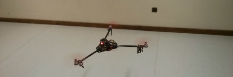
This test involve a motion capture system, Optitrack, that is hooked to Simulink via a QUARC block to get the attitude (6DOF) of the quadrotor, then we perform some calculations to estimate the position of the quadrotor and output the desired position, and we proceed to sent the commands, roll and pitch, via Bluetooth to the MW board, usign the RCSERIAL commands.
The first step is to make the quad remain in one position in space, in this case the center already setup of the motion capture system.
We had several crashes, one due to me, hehehe, and the other just for being very brave and test a flying quad for the first time (with no safety whatsoever). The 3D printed frame has proved to be very useful and easy to repair.
In the last test of the video (showed below) TEGOv3 does not lift off, to avoid unnecessary crashes, it will just hover enough for the quad to be able to perform ROLL and PITCH maneuvers. Its showed that the quad goes to the center marked on the floor, of course, we need to tune the gains for control and input the exact constants of this frame and motors combination.
Many thanks to my buddy and work colleague Murray and my sweet horde of undergrads .
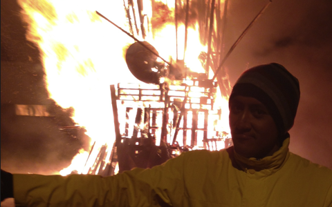
Your quadcopter might be cool, but not as cool as a quadcopter flying over a impressive bonfire (spoiler alert, duh)… Bonfire Night is an annual event dedicated to bonfires, fireworks and celebrations. Some of the world’s most popular Bonfire instances include Great Britain’s Guy Fawkes Night, which is a annual commemoration observed on 5 of November.
And my favorite skydiving airfield “Skydive Strathallan” could not stand behind… For them is an annual tradition, for me it was my first bonfire night, very fun and highly dangerous.
The main difference with this weekend at Strathallan is that I took my dear AlduxQuad with me… The rest is history. Its better if you watch the video, be warned, its a little long, 8 minutes and 34 seconds.
I was a little bit sad at the end of the summer, my favorite designer had left , so, to cheer me up, I start building a tricopter, using a carbon-fiber frame, some powerful motors, a digital servo, some ESC’s and a MW board…
The tricopter is a small model rotorcraft with three arms, this arms can be shaped (angled) as the letter Y, T, and in between, the angle in Y configuration is 120 degrees. The Y configuration brings to the system the best performance and simplest piloting.
The yawing of a tricopter is a special case. If you are using one rotor, it produces torque that tries to spin your vehicle into the opposite direction of the rotor. A helicopter uses its tail rotor to compensate this direction. A quadrocopter, hexacopter, octocopter an all copters with an even amount of rotors are using the fact that two rotors are in the same plane, both turning in opposite directions with the same speed, are neutralising their torque.
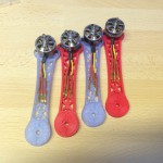
Arms and ESCs
Arms completed
Assembly almost ready
Ready
Uploading firmware
A tricopter has two rotors that are spinning in opposite directions (or in the same direction ) but there is a rotor left who produces torque that tries to spin the tricopter. Because of this, tricopters are usually using a rear servo to tilt the rear rotor to compensate this torque in the same manner a helicopter tail rotor does. The advantage of this solution is more yawing agility in comparison to multicopters with even amounts of rotors.
In the final tests of the maiden flight I change the angle of the arms, from \ | / to \ | | (asymmetrical arms) and I was able to fly it, but it was a little more complicated. When switching to the T configuration, the tricopter goes forward very very fast and its more hard to control and to hover it in place.
So, the main advantage of the tri is that the rear servo makes yawing much faster. And also are more agile than even-multicopters.
Thanks to Murray for sharing the maiden video, and giving me nice pointers to its dynamics.
http://vimeo.com/78837673
note: in the video edition I wasn’t able to remove the words “Great Britain”… sorry for that…
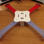
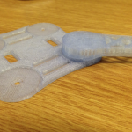
This is yet another version of a 3D printed quadrotor, pointed to be one of the workhorses of my research… The main characteristic of this frame is that instead of using nut and bolts to join the arms and the base together, like in TEGO v2, I’m using Rotite®s!!!!
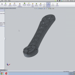
Designing arm
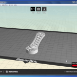
Printing arm
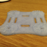
Baseplate
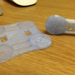
unlocked
base and arm
For those who don’t know what rotites are, you can give it a pick here, I was trying to find a solution to reduce weight of my previous TEGO v2 frame, and somehow I found this company, I immediately put in contact with them, and after several e-mail exchanges, phone calls and even videoconferences with the inventor, I was able to get my hands on some of their designs, there is a picture below where Stuart is giving me a lecture about Rotites.
So, I started playing in Solidworks, in conjunction with my favorite Industrial Designer, that was visiting me (it was on summer ), and we did this design, using 90 degrees A and B rotites, 4 B’s on the main plate and one B on each arm.
Then I order some more ESC and motors, exactly the same as the ones on TEGO v2, and put everything together. But… I did a critical mistake when soldering the motors, and it wasn’t flying, but, using the resources around me (undergrads, hehehe) I “kill to birds with one shot”, so, I teach them how to solder and the quad-ESC-motors basics, then we re-solder the motors and voila!!!! TEGO v3 is flying. Dont forget to check the video!!!
The weight was dramatically reduced, and the endurance dramatically increased!!!
Many thanks to Stuart Burns (inventor of Rotite®) and of course, the Rotite® company to letting me use their designs 🙂
This summer, I did a road-trip with some friends, across Scotland, and of course, I HAD to take my quad with me 😉
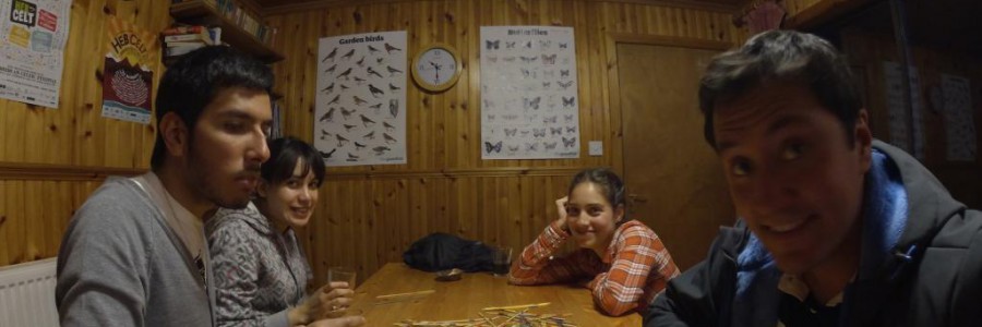
The main problem was that just one week before the roadtrip, I losted my gopro pivot adjust thumb screw… 🙁 So, I was unable to do too much flights because the GoPro was not attached… But I did a couple of flights, and this video shows the quad trying to integrate with a flock, hehehe, funny stuff, I actually thought they were going to attack AlduxQuad, but no…
And this flight occurred in our Hostel in Fort Augustus.


 .
.
 , so, to cheer me up, I start building a tricopter, using a carbon-fiber frame, some powerful motors, a digital servo, some ESC’s and a MW board…
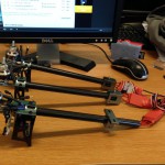

 ) but there is a rotor left who produces torque that tries to spin the tricopter. Because of this, tricopters are usually using a rear servo to tilt the rear rotor to compensate this torque in the same manner a helicopter tail rotor does. The advantage of this solution is more yawing agility in comparison to multicopters with even amounts of rotors.
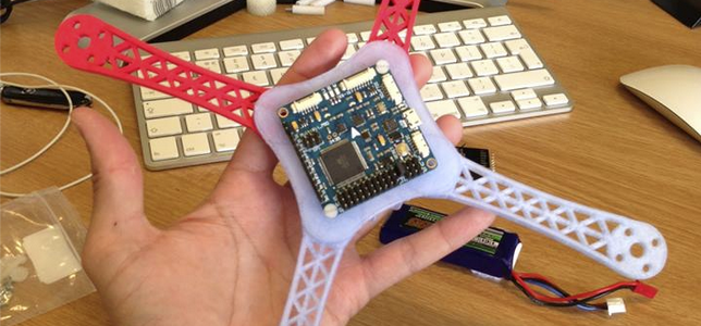
 ), and we did this design, using 90 degrees A and B rotites, 4 B’s on the main plate and one B on each arm.


